
What is the problem?
Three servers, three NVRs, three control panels: they all leave the factory with the same address, for example 192.168.1.1. For some reason, you cannot change it: the manufacturer’s software requires it, the installer is no longer available, or it is simply not your equipment. However, you must reach all three from the same PC, within the same LAN.
Connecting them to any switch is chaos: when asked “who is 192.168.1.1?”, three devices respond, and the PC talks to one a bit and to the other a bit. With a MikroTik instead of the switch, you see them as 192.168.1.11, .12, and .13, without touching the servers or the PC, and without leaving the LAN.
In the examples, the PC is 192.168.1.100 on ether1, and the three servers are on ether2, ether3, and ether4. A CRS switch or a router with multiple ports will do.
How does the trick work?
Two tools, one per layer:
- bridge NAT responds to ARP on behalf of the servers: when the PC asks “who is
.12?”, it replies “server 2”, with the real MAC of server 2. From that moment on, the PC sends packets for.12directly to server 2; - NAT IP changes the destination from
.12to.1while the packet traverses the bridge, so the server recognizes it as its own. On the return, the router restores the address, and the PC sees.12responding.
bridge NAT alone is not enough: it changes MAC addresses, never IP addresses, and the server would discard a packet for .12. NAT IP alone is not enough either: without someone responding to ARP, the PC would not know where to send the packets. Together, they do the job.
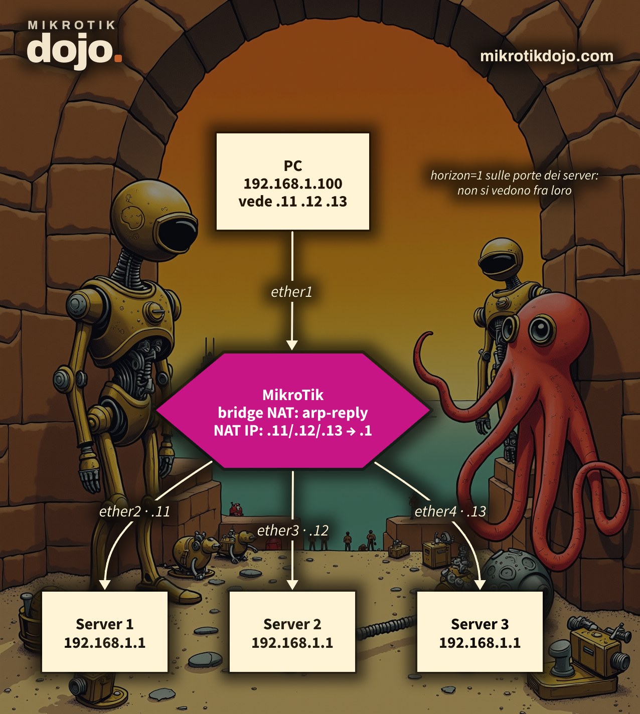
Step 1: what are the servers’ MACs?
You need the MAC of each server: usually, it is on the label. Otherwise, connect them to the MikroTik and check on which port each MAC appears:
/interface bridge host print where !localIn the examples: server 1 AA:AA:AA:00:00:01, server 2 AA:AA:AA:00:00:02, server 3 AA:AA:AA:00:00:03. Use yours.
Step 2: how do I connect the ports?
All four ports in the same bridge, but with the servers isolated from each other:
/interface bridge add name=bridge-lan
/interface bridge port
add bridge=bridge-lan interface=ether1 hw=no
add bridge=bridge-lan interface=ether2 horizon=1 hw=no
add bridge=bridge-lan interface=ether3 horizon=1 hw=no
add bridge=bridge-lan interface=ether4 horizon=1 hw=nohorizon=1: ports with the same horizon do not talk to each other. The three servers cannot see each other, so they do not fight over the address, but they all see the PC;hw=no: on a CRS switch, traffic that the switch chip forwards on its own never reaches the CPU, and therefore neither bridge NAT nor the firewall sees it. Withhw=no, it passes through the CPU. On a router without a switch chip, this parameter changes nothing.
I verified this on a real CRS switch, with a Prestera chip, using a camera instead of a server: with hw=no, the camera responds to the new address, ping, and web page; with hw=yes, ARP still works, but the chip delivers the packets without passing through NAT, and nothing responds.
And the switch’s port isolation (/interface ethernet switch port-isolation), instead of horizon? On the lab switch, it only works for traffic forwarded by the chip: with hw=no it is ignored, and the “isolated” port starts talking to everyone again. Here the CPU does the work, so you need horizon, which applies to the CPU bridge.
⚠️ Warning: if you are connected to the MikroTik from one of these ports, you will lose your connection for a moment. Work from another port, or via WinBox over MAC.
Step 3: how do I answer ARP on behalf of the servers?
One bridge NAT rule per server. It is a tailored proxy ARP: it responds only for that address, and with the MAC you choose.
/interface bridge nat
add chain=dstnat mac-protocol=arp arp-opcode=request arp-dst-address=192.168.1.11/32 \
    action=arp-reply to-arp-reply-mac-address=AA:AA:AA:00:00:01 comment="server 1"
add chain=dstnat mac-protocol=arp arp-opcode=request arp-dst-address=192.168.1.12/32 \
    action=arp-reply to-arp-reply-mac-address=AA:AA:AA:00:00:02 comment="server 2"
add chain=dstnat mac-protocol=arp arp-opcode=request arp-dst-address=192.168.1.13/32 \
    action=arp-reply to-arp-reply-mac-address=AA:AA:AA:00:00:03 comment="server 3"
Why not the classic interface proxy ARP (arp=proxy-arp)? Because it would respond with the MikroTik’s MAC, and the MikroTik would then have to route the packets: that is the other path, the one at the end of the article. Here, instead, the PC talks directly to the servers, and the MikroTik remains a switch. The arp-reply action is described in the MikroTik manual: Bridging and Switching.
Check addresses .11, .12 and .13: they must be free in the PC’s network. The Dojo IP calculator tells you if they are in the same subnet.
Step 4: how do I change the IP address inside the bridge?
By default, bridged traffic does not pass through the IP firewall: the bridge just forwards it. We make it pass through, and then we add a single NAT rule for all three:
/interface bridge settings set use-ip-firewall=yes
/ip firewall nat add chain=dstnat dst-address=192.168.1.11-192.168.1.13 \
    action=dst-nat to-addresses=192.168.1.1 comment="tre server"
One rule is enough because the server selection was already made by ARP: the packet for .12 is already addressed to server 2’s MAC, and NAT only needs to correct the IP. Without use-ip-firewall it does not work: in the lab, disabling it caused the ping to drop to zero and the counters on the servers to stop.
Step 5: how do I verify that each address leads to the right server?
From the PC:
ping 192.168.1.11
ping 192.168.1.12
ping 192.168.1.13
arp -a
arp -a must show .11, .12 and .13 with the MACs of the three servers, one different per address. But it is not enough that they respond: open the web page of each one and check that they are three different devices. In the lab, I sent 3, 4 and 5 pings to the three addresses, and exactly 3, 4 and 5 arrived on each server. The same with the web pages: 1, 2 and 3 connections, each to its server.
On the MikroTik, the counters show who did the work:
/interface bridge nat print stats
/ip firewall nat print stats
A curiosity you will see: in the PC’s ARP table, 192.168.1.1 also appears, with the MAC of one of the servers. This is normal: the servers, to respond, ask “who is .100?”, and the PC notes who asked. It does not cause issues, as long as you do not try to use .1 directly.
What if I do not want to be tied to MACs?
If a server fails and you replace it, the MAC changes and you must update its rule from step 3. If you prefer a solution that does not depend on MACs, there is the routed path: each server on a port outside the bridge, the MikroTik taking .11, .12 and .13 on the PC side, and a routing table per server, selected by mangle.
/ip address add address=192.168.1.11/24 interface=bridge-lan
/ip address add address=192.168.1.250/32 network=192.168.1.1 interface=ether2
/routing table add name=srv1 fib
/ip route add dst-address=192.168.1.1/32 gateway=ether2 routing-table=srv1
/ip firewall mangle add chain=prerouting dst-address=192.168.1.11 action=mark-routing new-routing-mark=srv1
/ip firewall nat add chain=dstnat dst-address=192.168.1.11 action=dst-nat to-addresses=192.168.1.1
/ip firewall nat add chain=srcnat out-interface=ether2 action=masquerade
The server 1 is shown above; for the others, repeat with .12/ether3/srv2 and .13/ether4/srv3, removing the three ports from the bridge first. I tested this in the lab as well, with the same result. The difference: the servers see all traffic coming from the MikroTik (192.168.1.250) instead of from the PC, and the three 192.168.1.1 are no longer on the same LAN as the PC. Tables and mark-routing are explained in the MikroTik manual: Policy Routing. And note: without mangle it seems to work, because all three addresses respond, but in the lab all pings ended up on the same server.
What do I check before putting it into production?
- NAT is not done in the chip: switch rules (
/interface ethernet switch rule) can steer traffic to the CPU or change its port and VLAN, but they do not rewrite MAC or IP. Hardware NAT exists only on some larger Prestera switches, and only for traffic routed with fasttrack; CRS3xx switches, like the one in my lab, do not have it. I also tried leaving the ports in hardware and sending only the server traffic to the CPU with a switch rule: it does not work; - everything goes through the CPU:
use-ip-firewallforces all bridge traffic through the firewall, andhw=notakes the work off the switch chip. For management, web pages, and cameras, this is fine; for moving gigabytes of backup, it is not. Keep only the necessary ports in the bridge; - as soon as possible, the real solution remains changing the server addresses. This is a fix, not a design;
- the MikroTik in the middle is the point to protect: if you have not done it yet, follow the Basic Hardening of a MikroTik Router.
Tested in the lab on PNETLab with CHR RouterOS 7.24.5 (stable): a Debian 12 client as the PC and three CHR instances with the same address as servers, connected on three separate VLANs instead of three ports. With bridge NAT: ping and HTTP to the three addresses, each arriving at the correct server (verified with server counters), and the test without use-ip-firewall, which does not work. With routing: same result, and the test without mangle, with all traffic ending up on the first server. On a CRS switch with a Prestera chip and RouterOS 7.24.5 and a camera as a server: bridge NAT trick working with hw=no and not with hw=yes, port isolation effective only with hw=yes, switch rules with redirect-to-cpu not sufficient.
Frequently asked questions
How do I reach multiple devices with the same IP address on the same LAN?
With a MikroTik instead of the switch: bridge NAT answers ARP for a different address for each device (action=arp-reply with the device’s MAC), and with use-ip-firewall=yes a dst-nat rule restores the destination to the real address. The device ports must be separated from each other with horizon.
Is bridge NAT alone enough?
No. Bridge NAT only changes MAC addresses: the device would receive a packet for an IP that is not its own and discard it. You also need IP NAT, which sees bridged traffic only with use-ip-firewall=yes.
Why do CRS switches need hw=no?
Because traffic forwarded by the switch chip does not reach the CPU, and therefore does not pass through bridge NAT or the IP firewall. With hw=no on the involved ports, the CPU forwards it.
Can I use the switch’s port isolation instead of horizon?
Not in this case. Port isolation works in the switch chip and is ignored when the ports are hw=no; the NAT trick requires traffic to pass through the CPU, where isolation is handled by horizon.
Do I need to change anything on the servers or the PC?
No. The PC sees three normal addresses on its network; the servers see the PC arriving with its real address and reply directly to it.